F1Tenth Hardware Documentation
Disclaimer
This document is intended to serve as a simple guideline for new members, not as a comprehensive documentation of the entire car's
hardware. Therefore, only the most important details will be
presented, and it will not include instructions on how to perform a
complete teardown of the car.
Some basic information will be provided for those who have never used a screwdriver or connected a cable. These instructions will neither be complete nor fully accurate; they are merely intended to ofer suggestions to people with no prior practical experience.
Warning
This document is a work in progress. If you fnd any errors, or if you believe something is missing or unclear, please report them.
Basic guidelines
Screwdriver
Make sure to use the correct screwdriver for the job. The main types of screwdrivers, along with their corresponding screws and symbols, are shown in the fgure below.
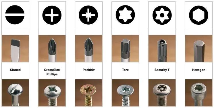
If you don't use the right tool, you can damage the screw and, less often, the screwdriver. For example, a slotted screwdriver can be used on a Phillips screw, but it is not the correct tool, and you may damage both. Similarly, you could attempt to use a Torx screwdriver on a hexagon screw, but in this case, only the corners of the screwdriver will make contact with the screw, potentially causing damage to both. Once again, be sure to use the correct tool.
Pay attention also to the size of the screwdriver. Always try to use the largest screwdriver that fts properly into the screw (it must not be too large). In this way the contact surface between tool and screw will be maximized.
Try to apply the right amount of force (never tight the screw too much)and AVOID SLIPPING between the screw and the screwdriver. Due to wear and to slipping, the screw becomes stripped.
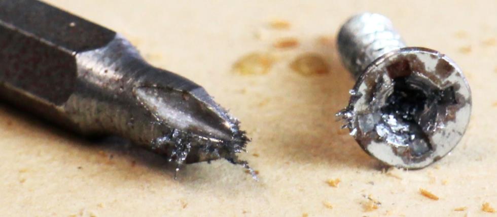
In this case, it will be very dificult to unscrew it… In case this happens there are several techniques to remove the screw, but the best thing is to avoid damage and to not use screws that are already damaged. Pay attention please.
Battery charging
Here will be considered one of the two battery charger that the team currently have. It is better than the other because it shows the voltage of the battery.
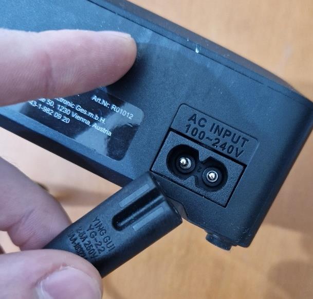
1) Connect the AC cable to the battery charger. The direction does not matter. Then connect the AC cable to the power greed.
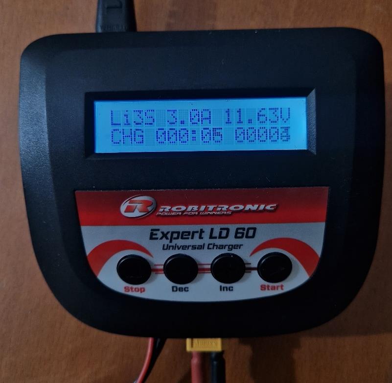
2) At this point the battery charger will emit a sound and the display will turn on. This program should be displayed.
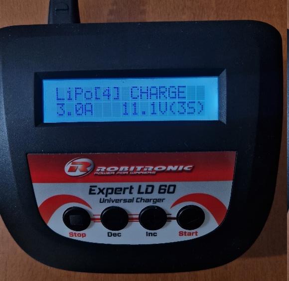
The battery that the team has are LiPo, 3 Cell, 11.1V, 5000mAh, 50C. The settings you see are for this type of battery and the charging current is set to 3.0A just to be keep the battery safe. In theory, is possible to increase this value but the suggestion is to keep those settings.
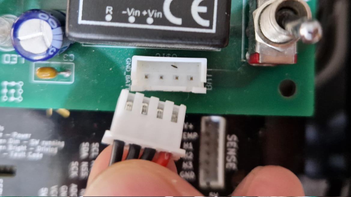
3) Connect frstly the power cable (yellow one) and the balancing cable (the white one).
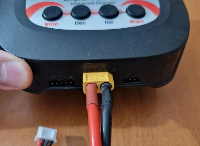
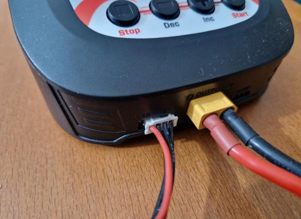
As you see, both have a particular form, and it will be hard to connect them wrong. Just pay attention to the white cable: it needs to go on the right of the connector with the black cable on the right and the red on the left. The rightest pin of the charger bust been left empty: that is needed for a 4 Cell battery.
4) Now press the start button and keep it pressed until the charger check the battery and ask for a confrmation.
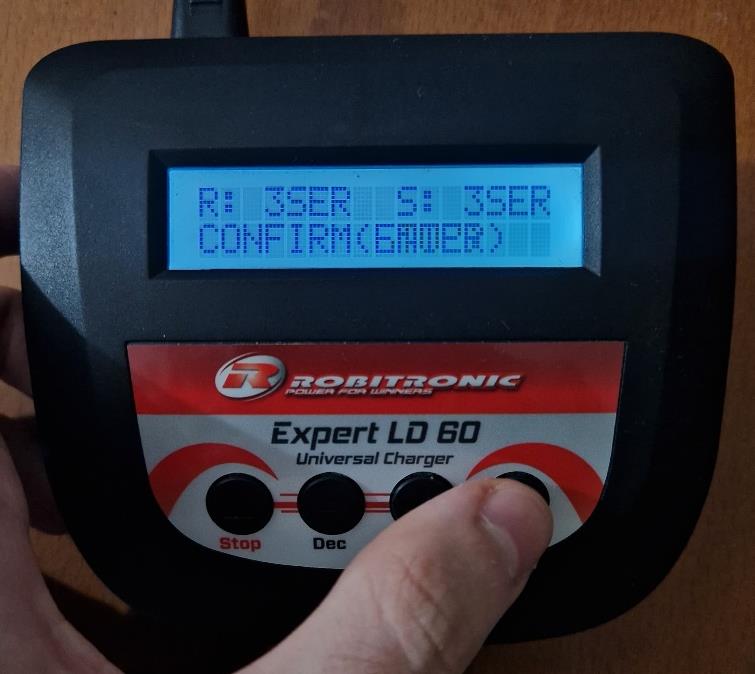
Then, press again the start button until the charger makes a sound. The charging process will start.
5) When the charging process will be completed the charger will make a long sound to indicate that the battery is full. At this point you can press stop ad simply detach the battery. If you need to stop the charging earlier, use the stop button and then detach the battery.
Warnings: The voltage level of the battery should not go below to 10.5V - 10.0V let’s say (to keep the battery very safe). This because LiPo battery got damaged if they are discharged too much.
Moreover, in any case, the car will stop working if the battery voltage will drop under 9.0V (it will be shown why this happens next). For this reason, check the battery voltage frequently by using the right ROS2 topic, through a multi-meter or using the LED we built for this purpose (if it is present and connected).
Car power connections
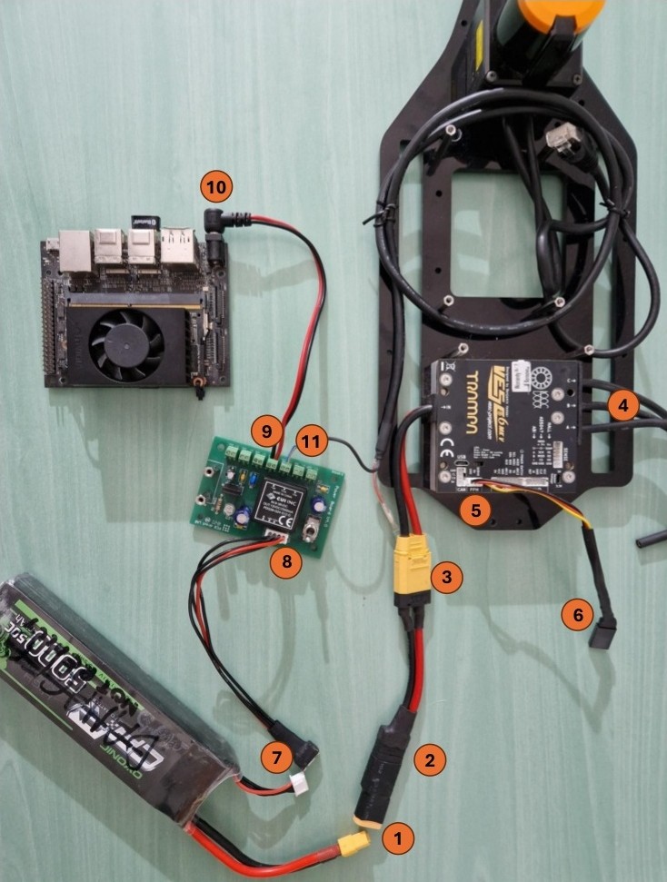
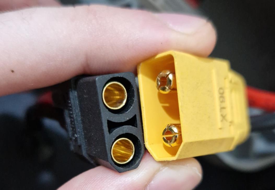
1) Power connector of the battery. It will supply the Vesc and, consequently, the motor and the Vesc but not the Jetson. This connection is just an adapter. To disconnect the battery, use this instead of the connection 2 or 3. This because it is simpler and those connectors are ambiguous, in particular the number two, and can happen to connect it in the wrong way.
2) Just an adapter. Pay attention to the polarity
3) Another adapter. The yellow part is the connector of the Vesc
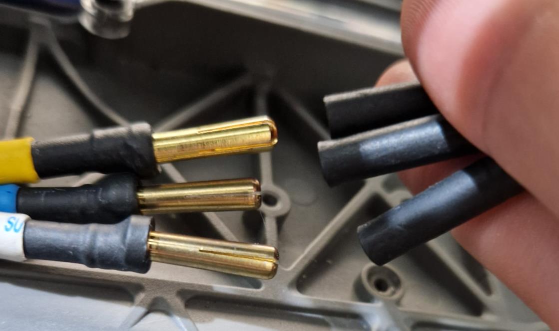
4) Connection to the motor. It does not matter in which order you connect the three cables. The only “bad” thing that can happen is that the motor (and so the wheel) will start to spin in the wrong direction. To correct this behaviour just fip two of them randomly. This will change the direction of rotation of the magnetic feld of the motor, and it will run in the correct way (you should study electric motor by the way. Beautiful subject if you don’t need to do an exam on it)
5) Connector for the servo. It goes in “PPM”.
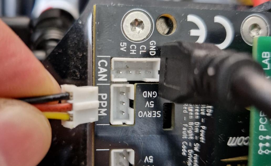
6) Servo connection, just an adapter. It has a specifc form so there isn’t the risk to attach it in a wrong way

7) Connector of the battery for the power supply of the Jetson and the LiDAR. It goes to an adapter. The adapter is connected to the power supply board through 8
8) Connector of the adapter to the power board.
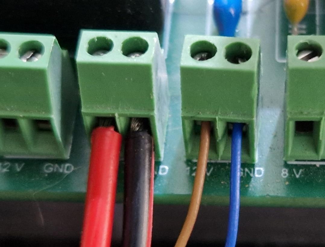
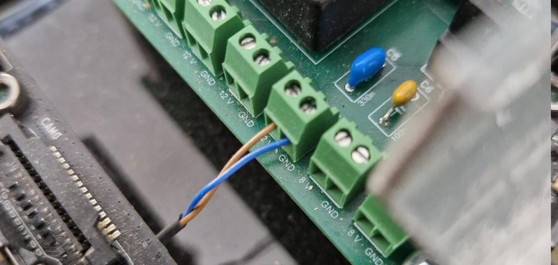
9) And 11) are displayed below. PAY ATTENTION. On the right we have the connector for the Jetson. The red cable goes to 12V and the black cable to GND. On the left we have the power supply of the LiDAR. Brown cable to 12V and blue cable to GND.
10) Just the connector of the power supply board to the Jetson.
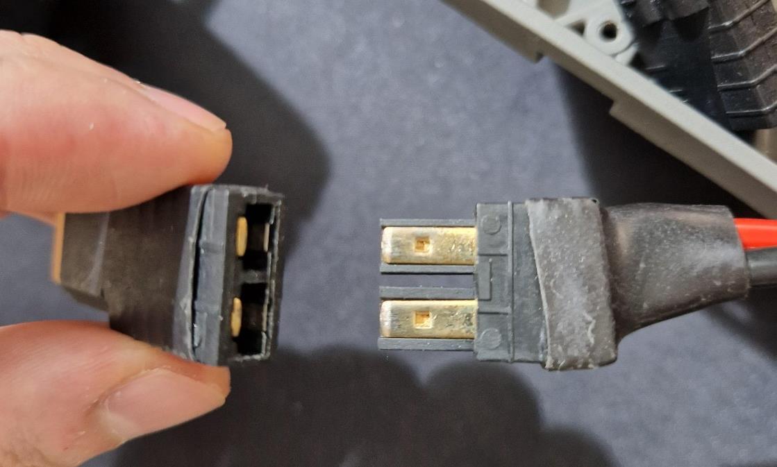
Alternative battery connection

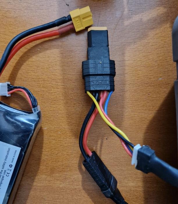
Take in the connection 7) the cable that goes to the power supply board and attach it to 13). Then, in connection 2) the right connector in the photo needs to be attached to 14). Finally, the left connector of the connection 2) needs to be connected to 12).
In this way you can connect the battery just with one cable (the yellow one of the battery).
Problem: this connector is damaged, don’t use it. A cable does not make contact in a good manner.
Power supply green board
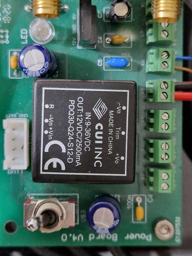

The power supply board can be seen, in frst approximation, as one DC/DC converter and one voltage regulator that are connected to the battery when the switch is turned on. If the switch is on, also the LED turns on.
The 12V DC-DC converter is the one that supply both LiDAR and
Jetson. It is a switching regulator that keeps the voltage constant at
12V if the input voltage (battery voltage) it is between 9V and 36V. For this reason, the car turns of if the voltage of the battery is under 9V.
It can provide a maximum power output of 30W, they are suficient for
our Jetson and the LiDAR but pay attention if you need to connect
other things. In any case, a heat sink placed on it would be nice.
The voltage regulator is a dissipative component to regulate the voltage, in this case at 8V. From datasheet it can provide a maximum current of 1A (so 8W is the maximum power). We are not using it but pay attention
Car signal connections
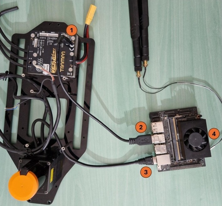
1) Micro-Usb connection to the Vesc
2) Usb-A connection to the Jetson for the Vesc
3) Rj45 connection for the LiDAR
4) Antennas connection
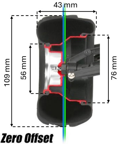
Tires specifcation and tuning
WHEELS AND TIRE PARAMETERS
• 12mm hex (VERY IMPORTANT, it is the dimension of the nut of our car to which we need connect the wheel)
• Original ofset parameter not found (It is not important as long as the wheel does not interfere with suspension/steering mechanism)
• Original tire dimensions: 4.3” x 1.7″ (109 mm x 43 mm)
• Changing tire diameter could lead to an increase/decrease of the speed / non-optimal gear ratio. Larger tires increase the fnal gearing (top speed and load are increased) and smaller tires reduce it (better acceleration and fnal gearing is reduced). The better acceleration is caused by a larger force applied on the foor, that means that we are more prone to slipping. Moreover, if we decrease the tire diameter it’s important to check that the base of the car does not touch the foor.
In every case if we change the tire diameter, we need to check the Vesc confguration and monitor the condition of the motor (in particular if we increase the diameter and so the load). There is also the option of changing motor gearing but it’s dangerous in my opinion. All the four wheels need to have the same tire dimension, otherwise the smaller tire will slip continuously
• Changing the tire width it’s ok as long as that does not interfere with suspension/steering mechanism
• Original wheel Diameter: 2.2” (56 mm) (outer) 3.0” (76 mm) (inner)) (not really important if we don’t replace only the tire and
we WON'T do that, otherwise we need to buy the exact type of tire and also the glue to substitute it
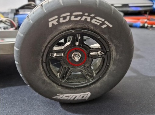
To dismount the wheels just unscrew these nuts.
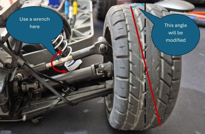
CAMBER ANGLE TUNING
Camber
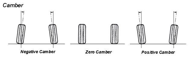
This operation is possible on all the four wheels. If they are brought outward vertically so negative camber (“legs wide”) we have more grip and more friction. An angle between 0.5° and 1.5° is good. Negative camber improves handling by keeping the tire perpendicular to the road as the car rolls; ensuring that the tire's contact patch is evenly loaded.Without adequate negative camber the tire would load the outer portion of the tire and produce less grip. Adding too much negative camber will reduce the peak tire grip during straight-line acceleration and braking.
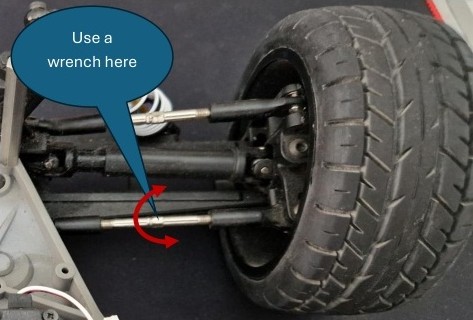
TOE ANGLE TUNING
That is only for front wheels. Toe is the measure of how far inward or outward the leading edge of the tire is facing, when viewed from the top. It has a large efect on how the car reacts to steering inputs as well as on tire wear.

Toe-in is when the leading part of the tire is turned inwards towards the centre of the car. This makes the tires want to push inward, which acts to improve straight line stability of the car as its traveling down the road, particularly at high speed.
Toe-out is when the leading part of the tire is turned outwards away from the centre of the car. This makes the tires want to separate from each other. This improves turn-in response considerably, but at the cost of tire wear.
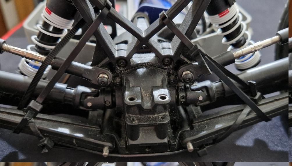
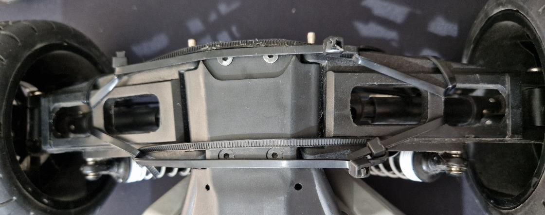
LiDAR positioning problem
To work correctly, the LiDAR must be positioned with the scan plane parallel to the ground. That is quite intuitive: if the LiDAR scan plane points up-word, it will not see the tubes and the opponent after a certain distance. If it points down-word, it will see the foor. It also must be positioned at the right height for obvious reasons.
What is not intuitive is that during accelerations, breaking and turns, due to the suspension system the angle of the plane on which the LiDAR is mounted is modifed. This causes a loss of the wanted alignment of the LiDAR plane with a subsequent wrong measurement.
To solve this problem efectively, it is necessary to rearrange the chassis and change the suspension system. For the moment what has been done is to fx the suspension system using cable ties.
How to dismount the car
In this version only the main passages will be shown. To mount the car back again try to use this passages backword following what you need. Most of the passages are not in a precise order.
BEFORE MOVING ON DETACH THE BATTERY
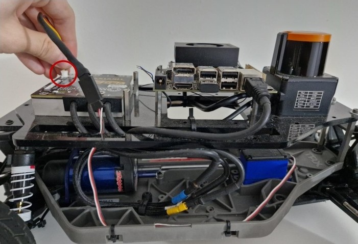
1) Remove the cover and the LEDs connection. Pay attention during this since the pins of the Nvidia Jetson are not so robust.
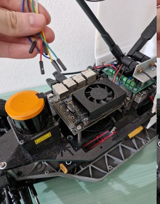
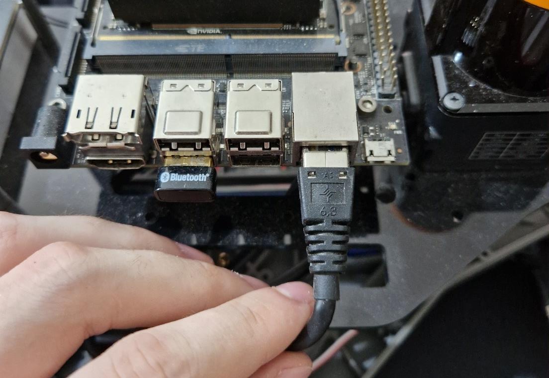
2) Detach the Vesc USB cable
3) Dismount the antennas by rotating them. Pay attention to the “gold” connection and to the cable connected to them. Hold the nut at the side of the cable while you are dismounting the antenna to avoid twisting the cable.
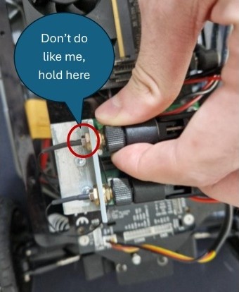
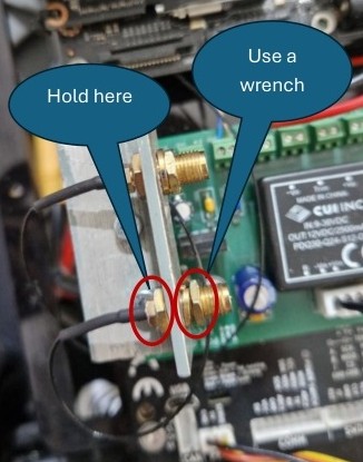
Then, turn the other gold nut while you hold the same nut as before. For this is better to a wrench.
4) Dismount the battery cable of the Jetson power supply board.Just pull but be careful.
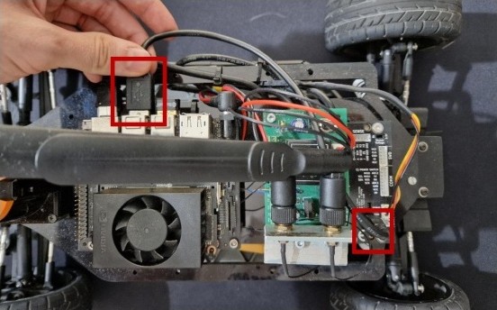
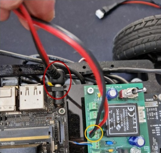
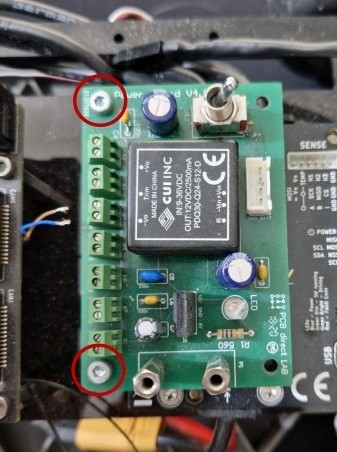
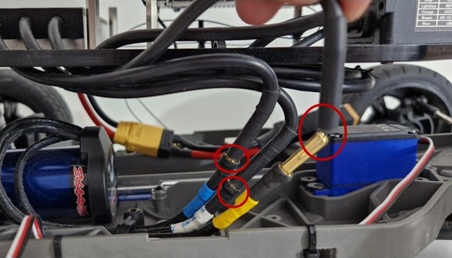
5) Detach the power cable of the Jetson. The Jetson has classical connector while to detach the cable from the power supply boars a screwdriver is needed (orange circle). When you attach back this cable, PAY ATTENTION TO THE POLARITY! So, you need to connect the red cable to 12V and the black cable to GND
6) Detach the LiDAR power supply cable. When you attach back this cable, PAY ATTENTION TO THE POLARITY! You need to connect the brown cable to 12V and the blue cable to GND.
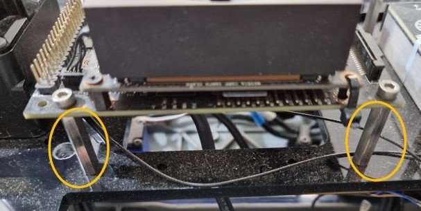
7) Dismount the antenna holder by unscrew the two screws indicated in red. To be sure, hold the other side of the spacers with a hand, indicated in blue while unscrew.
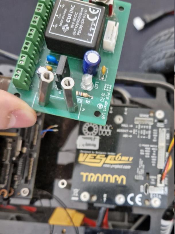
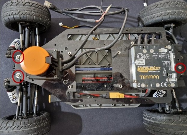
8) Dismount the green power supply board by unscrew the two indicated screws.
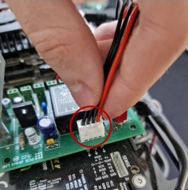
9) Detach the servo power cable. You simply need to pull it but be careful.
10) Detach the three cables of the motor that are connected to the Vesc. You don’t need to remember the order or how they are attached to the Vesc.
11) Detach the rj45 cable of the LiDAR form the Jetson
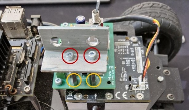
12) Dismount the Jetson. BE CAREFUL, YOU WILL HAVE AROUND 600 EUROS in your hand with a shipping time of 6 month, IF YOU BREAK IT, THEN YOU ARE DEAD. You need to unscrew these four screws.
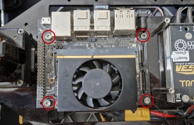
While you are doing this, as usual, hold the spacers to be sure.
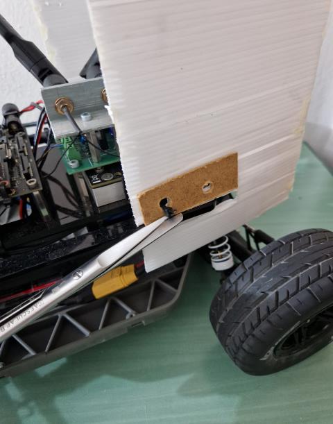
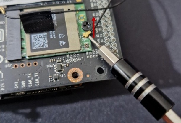
13) Now we need to detach the antenna from the Jetson. PAY ATTENTION. REALLY. ATTENTION PLEASE. Put the Jetson on fat plane in an upside-down position. Use a small fat screwdriver to detach the antenna connector. Put the tip under the cable and carefully arise the tip untill the cable is detached.
14) Detach the plan from the car. There are three (should be four)screws. The two on the front have a washer. Don’t lose them, they are needed to distribute the force of the screw on higher area and to not damage the black plate. The screw in the back is not really attached, however at this moment there is a small piece of plastic used as a spacer. Don’t lose it.
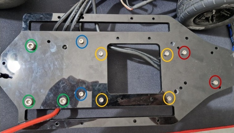
15) By put the plane upside down we can see the screw to dismount the LiDAR (Red) and the Vesc (Green) from the plane.
We can see also the screws for the spacer of the Jetson (Orange)and the screw for the spacers of the green power board (Blue). It is suggested to dismount them only if needed.
16) To dismount the wheels just unscrew these nuts.
Transmission system overview
Almost all the information that are reported here are being taken directly from the documentation of the Traxxas Slash 4x4.
To recap, the motor has a pinion that is connected to the spur gear of the clutch (yes there is a clutch system). The clutch is connected to a transmission bar that gives power to both front and rear wheels. Both front and rear wheels are equipped with a diferential system.
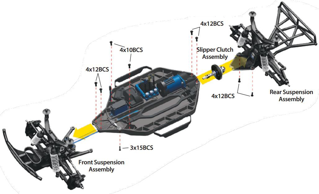
Removing the front suspension module
-
Remove the two 4x12 button-head cap screws from the front of the chassis.
-
Remove the two 4x10 button-head cap screws from the top of the chassis.
-
Remove the 3x15 button-head cap screw from the steering link under the chassis.
-
Pull the front suspension assembly away from the chassis.
Removing the rear suspension module (Slipper clutch assembly removal)
-
Remove the two 4x12 button-head cap screws from the top of the chassis.
-
Remove the two 4x12 button-head cap screws from the bottom of the chassis.
-
Pull the rear suspension assembly away from the chassis.
-
The slipper clutch assembly can now be removed.
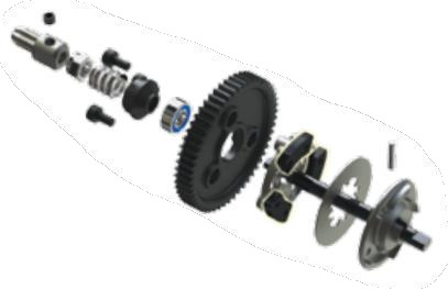
Slipper clutch
Under normal use, the friction material in the slipper clutch should wear very slowly. If the thickness of any one of the slipper clutch pads is 1.8mm or less, the friction disc should be replaced.
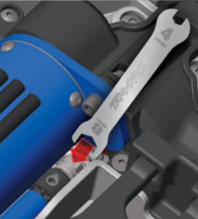
Adjusting the Slipper Clutch
The model is equipped with an adjustable slipper clutch which is built into the large spur gear. The purpose of the slipper clutch is to regulate the amount of power sent to the wheels to prevent tire spin. When it slips, the slipper clutch makes a high-pitch, whining noise. To adjust the slipper, use the included wrench to hold the adjusting nut and roll the model forward to tighten and reverse to loosen. Place the model
on a high-traction surface, such as carpet. Adjust the slipper so that you can hear it slip for approximately two feet from a standing, full throttle start. (Learn more about adjusting the slipper clutch in the sidebar.)
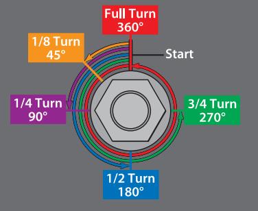
To achieve a good starting point for the slipper clutch in this model, remove the slipper gear assembly from your model and tighten the
slipper clutch adjusting nut clockwise until the slipper clutch
adjusting spring fully collapses (do not over tighten), and then turn the slipper clutch nut counterclockwise one full turn.
Do not run your model with the slipper clutch adjusting spring fully
compressed. The minimum recommended slipper clutch setting is
1/2 turn counterclockwise from fully compressed.
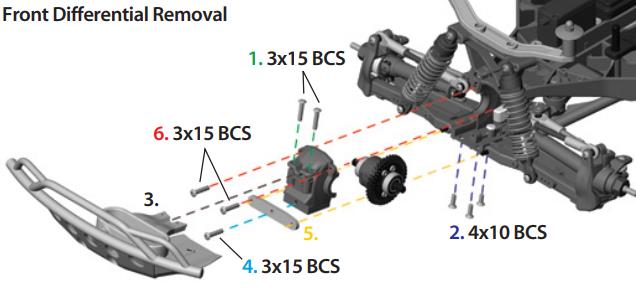
Front diferential
-
Remove the two 3x15mm button-head screws that secure the top bumper mount to the diferential (dif) case.
-
Turn the chassis over and remove the three 4x10mm countersunk screws that hold bumper/skid plate to the bulkhead. The two rear screws do not need to be removed.
-
Slide bumper assembly of of the chassis.
-
Remove 3x15mm button-head screw from dif tie bar.
-
Slide tie bar of truck.
-
Remove two 3x15mm button-head screws from dif cover. Do not remove the two screws that secure the shock tower.
-
Use a 1.5mm hex wrench to remove the two screw pins that hold the driveshaft yokes to the diferential output shafts. Remove the diferential cover and slide the diferential out of the front of the case.
-
To reinstall the diferential, reverse the steps.
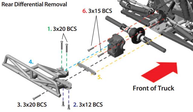
Rear diferential
-
Remove the two 3x20mm button-head screws that secure the top bumper mount to dif case.
-
Turn the chassis over and remove the two 3x12mm countersunk crews that hold the bumper/skid plate to the bulkhead. The two front screws do not need to be removed.
-
Remove the 3x20mm button-head screw from the bumper mount and tie bar.
-
Slide bumper assembly of of the chassis.
-
Remove the tie bar from the chassis.
-
Remove the two 3x15mm button-head screws from diferential cover. Do not remove the two screws that secure the shock tower.
-
Remove the diferential cover and slide the diferential out of the front of the case.
-
To reinstall the diferential, reverse the steps.
Other considerations
The diferential is flled with some fuid. In the manual is possible to fnd the procedure to substitute it:
Reflling the diferential:
-
Remove the four 2.5x10mm screws from the diferential case and carefully pull the dif case halves apart. Work over a towel to collect any fuid that drips from the diferential.
-
Drain the fuid from the diferential. You may wish to remove the spider gears from the diferential to make this easier.
-
Place the spider gears back into the dif case (if you removed them). Fill the dif case with fuid until the spider gears are submerged halfway.
-
Rejoin the dif case halves, using care to align the screw holes. Be sure the rubber gasket is in place, or the diferential may leak.
-
Install the 2.5x10mm screws and tighten securely.